
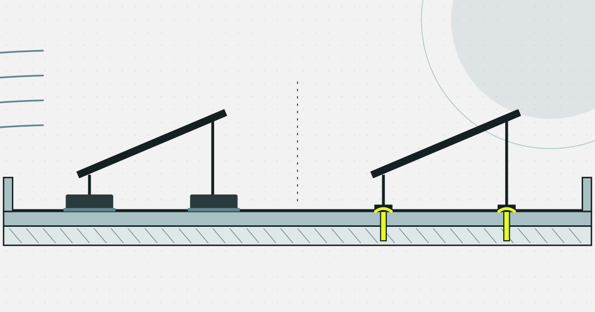
On a flat commercial roof, the choice between a ballasted and a mechanically attached PV mounting system comes down to three questions: how much additional load the roof structure can carry, how strong the wind loads are for that building and location, and whether the roof membrane may be penetrated. Ballast avoids penetrations but adds weight. Anchors save weight but require sealed roof penetrations. Many projects end up with a hybrid of both.
This guide walks through how each approach works, where each one fits best, and what installers, EPC contractors and designers should verify before ordering a mounting structure. If your main constraint is the weight of the modules themselves, see our separate article on lightweight PV modules for roofs with limited load capacity. Here the focus is the mounting method.
What mounting systems are used on flat roofs?
Flat-roof PV structures fall into three families. Ballasted systems stand on the roof surface and are held in place by weight, usually concrete blocks or ballast trays, combined with an aerodynamic design that reduces wind uplift. Mechanically attached systems are fixed to the building structure with anchors that pass through the roof build-up into the concrete slab, steel deck or purlins below. Hybrid systems combine both: the array is mostly ballasted, with a limited number of anchors in the zones where ballast alone would become too heavy.
Layout matters as much as the attachment method. South-facing rows at a moderate tilt maximise yield per module but catch more wind and need wider row spacing to avoid shading. East-west arrays sit lower, with modules leaning against each other in a tent-like profile. They tend to be aerodynamically calmer, use roof area more densely and spread production more evenly across the day, which is often attractive for buildings with daytime consumption. The layout choice directly changes the wind load and therefore how much ballast or how many anchors a system needs.
How does a ballasted system work?
A ballasted system resists two forces: wind uplift, which tries to lift the array, and wind-induced sliding, which tries to push it across the roof. Weight counters uplift, while friction between the structure's support pads and the roof surface counters sliding. That is why the contact material matters. Protective mats or pads must suit the membrane type, protect it from abrasion and provide the friction the structural calculation assumes.
Ballast is never distributed evenly. Wind pressure on a roof is highest at the corners and edges and lower in the central field. A correct ballast plan therefore places considerably more weight along the perimeter, and some layouts keep the edge zone free of modules altogether. The amount of ballast at each support point should come from a wind calculation for the specific building, based on EN 1991-1-4 with its national annex, the building height, terrain category and the array geometry. It should not come from a rule of thumb copied from a previous project.
The big advantage is that the roof covering stays intact. There are no holes to seal, no thermal bridges through the insulation and usually fewer questions from the roofer or the roof warranty provider. Installation is also fast: the structure is assembled on the roof and weighted down without drilling into the building.
When is mechanical attachment used?
Mechanical attachment becomes the better option when the weight budget runs out. Many logistics halls and production buildings with light steel roofs were designed with little reserve for additional permanent load. On such a roof, the ballast needed to secure an array in the edge and corner zones can simply exceed what the structure can safely carry. Anchors transfer uplift forces directly into the load-bearing structure, so the added dead load stays low.
Anchoring is also common on tall buildings, in exposed coastal or open-country locations and on roofs with a slight pitch, where sliding risk grows. The trade-off is the roof penetration. Every anchor has to be sealed with a detail compatible with the existing membrane, ideally carried out or approved by a roofing contractor, and agreed with whoever holds the roof warranty. This adds coordination and labour, but on the right roof it is the only safe solution.
Ballast or anchoring – how do they compare?
The table below summarises the typical differences. Treat it as a starting point for discussion with the structural engineer, not as a substitute for the project calculation.
| Criterion | Ballasted system | Mechanically attached system | Hybrid system |
|---|---|---|---|
| Roof penetrations | None | Yes, at every anchor point | Limited to selected zones |
| Added permanent load | Highest | Lowest | Moderate |
| Typical roof | Concrete slabs and roofs with load reserve | Light steel roofs with limited reserve | Roofs with reserve in the field but not at the edges |
| High wind exposure | Requires heavy edge ballast | Handled by anchors | Anchors where ballast would be excessive |
| Installation | Fast, no drilling | Slower, sealing details required | In between |
| Roof warranty | Usually simplest to agree | Needs approved sealing details | Needs approval for anchor points |
The pattern is clear: ballast trades weight for simplicity, anchoring trades simplicity for weight savings. The hybrid approach is often the most economical answer on larger roofs, because the central field, where wind loads are lowest, can be ballasted lightly while anchors take care of the critical perimeter.
How do wind, snow and roof load capacity affect the choice?
Wind sets the required resistance to uplift and sliding, and it varies with location, building height, surrounding terrain and position on the roof. Snow adds a second layer. Under EN 1991-1-3, snow can accumulate and drift behind parapets, roof steps and the module rows themselves, creating local loads well above the uniform snow load for the region. The structure has to carry the snow on the modules, and the roof has to carry the snow, the PV array and the ballast together.
Picture two projects scheduled for the same month. The first is an office building in a city centre with a reinforced-concrete roof and a generous load reserve. A ballasted east-west array is the natural fit: no penetrations, quick installation and a calm aerodynamic profile. The second is a logistics hall in an open, windy location with a light steel deck. Here the edge-zone ballast from the wind calculation would exceed the roof's capacity, so the project needs anchors along the perimeter, either as a hybrid or as a fully attached system. Same product category, opposite answers, because the building, not the installer's preference, decides.
What should you check before ordering a mounting structure?
Start with a structural assessment of the roof's load capacity from a qualified engineer. Without it, any ballast plan is guesswork. Then document the roof itself: the type and condition of the membrane, the insulation build-up, the roof pitch, drainage points and the height of parapets. Note the building height, the wind and snow zones for the location and any planned access paths, fire-safety clearances or maintenance routes that must stay free of modules.
On the PV side, fix the module model early, including its dimensions, weight and the clamping zones approved by the module manufacturer, because the structure has to match them. Decide on the layout, south-facing or east-west, with the energy yield and the client's consumption profile in mind. Finally, talk to the roofer and the roof warranty holder before the design is frozen, not after the structure has been delivered. These checks take days. Fixing a wrong mounting choice after installation takes far longer.
Regulation is adding urgency to these decisions. The EU's recast Energy Performance of Buildings Directive provides for a gradual extension of requirements for solar installations on buildings, taking into account their technical and economic feasibility. For owners of commercial buildings, this means flat-roof PV is increasingly a planning question rather than an optional extra, and choosing a mounting method that suits the roof becomes part of that planning.
Photonica solutions for flat roofs
Photonica designs and supplies its own PV mounting structures, including systems for flat roofs. Our flat-roof portfolio covers ballasted and bolted structures set at an optimal tilt angle, without penetrating the roof covering. Photonica Light Tension is a robust and flexible mounting solution for flat-roof PV installations. It features an additional ballast platform with an optional welded anchoring method and offers multiple mounting options, including clamps and rivets, ensuring durability in all zones.
Light Tension has been used, for example, on a 10.44 kWp installation in Bogatynia, Poland, and on a flat-roof project in Vilnius, Lithuania. Both are shown in our projects section. If you are preparing a flat-roof project, send us the roof data and the module model, and our team will help you choose the right mounting configuration.